
Pinpoint testing with wiring diagrams helps you efficiently locate electrical issues by visually tracing circuits and verifying component connections. Start by studying the diagram to understand the circuit layout, then follow the wiring path to test continuity, voltage, and resistance at key points. Use a multimeter guided by the diagram to identify breaks, shorts, or faulty components. Continue exploring, and you’ll gain the skills to troubleshoot electrical problems quickly and accurately.
Key Takeaways
- Use wiring diagrams to identify specific circuit pathways and component locations for targeted testing.
- Follow wiring routes visually to verify continuity and detect breaks or shorts accurately.
- Cross-reference color codes and pin configurations to ensure correct testing points.
- Systematically check voltage and resistance at key points to isolate faults efficiently.
- Combine circuit analysis with wiring diagrams to confirm component functionality and pinpoint issues precisely.
Have you ever struggled to locate an electrical problem in your vehicle or appliance? If so, you know how frustrating it can be to chase down issues that seem hidden beneath the surface. That’s where wiring diagrams come into play, acting as your road map to understanding complex electrical systems. When you’re ready to pinpoint the exact problem, mastering circuit analysis becomes essential. Circuit analysis involves systematically examining each part of the circuit to see how current flows and where it might be interrupted. By combining circuit analysis with troubleshooting techniques, you can considerably reduce the time and guesswork involved in fixing electrical issues.
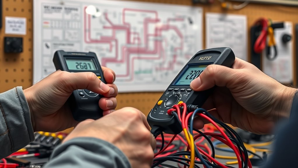
Using wiring diagrams, you can visualize the entire electrical pathway, from power sources to loads, and identify key components like switches, relays, fuses, and connectors. These diagrams highlight the color codes, pin configurations, and wire lengths, helping you trace the circuit step-by-step. When performing troubleshooting, it’s important to verify that each segment of the wiring is functioning correctly. This means checking for broken wires, loose connections, or corrosion that could be causing an open circuit or short. Instead of randomly replacing parts, you can methodically test each section using a multimeter, guided by the wiring diagram to know exactly where to test.
Using wiring diagrams helps trace circuits and verify component functionality step-by-step.
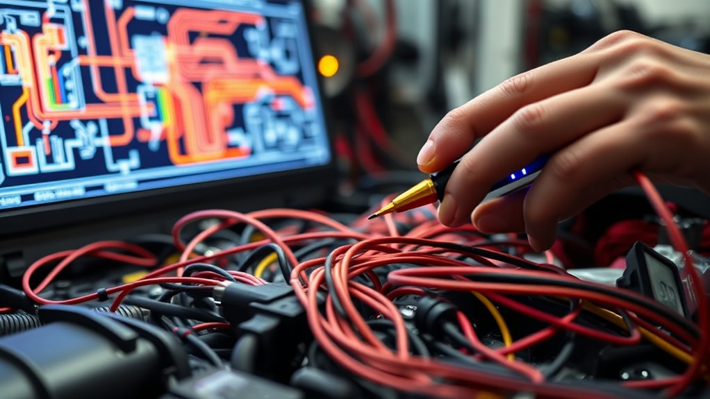
Troubleshooting techniques become more effective once you understand the circuit layout. For instance, you might start by checking the power supply with the diagram in hand, ensuring voltage is reaching the circuit. Next, follow the wiring to the switch or relay, testing continuity and resistance along the way. If you find a fault, you can isolate it precisely, saving you from unnecessary replacements. Using wiring diagrams also helps you understand how different components are interconnected, which is critical when diagnosing complex issues like intermittent failures or multiple faulty parts.
Moreover, circuit analysis allows you to predict how the system should behave under normal operation. If it doesn’t, you’ll know where to focus your troubleshooting efforts. This systematic approach enhances your problem-solving skills and gives you confidence that you’re not overlooking hidden faults. Understanding Honda Tuning modifications and upgrades can also influence how you approach electrical troubleshooting, especially in tuned vehicles where electrical modifications can introduce unique issues. Over time, as you become more familiar with reading wiring diagrams and applying circuit analysis, troubleshooting becomes faster and more accurate. You’ll develop an intuitive understanding of electrical systems, making pinpoint testing with wiring diagrams a powerful tool in your repair arsenal.
Frequently Asked Questions
Can Wiring Diagrams Be Used for Troubleshooting Complex Electrical Systems?
Yes, wiring diagrams are essential for troubleshooting complex electrical systems. They help you identify issues quickly by showing connections and component functions, but you must prioritize electrical safety and guarantee diagram accuracy. Always verify the diagrams are up-to-date before starting work, and follow safety protocols. Using accurate wiring diagrams allows you to pinpoint problems effectively, reducing risks and preventing damage to the system during troubleshooting.
What Tools Are Essential for Effective Pinpoint Testing With Wiring Diagrams?
Imagine opening the secrets of your electrical system—you’ll need essential tools. A multimeter is your best friend for accurate readings, so make sure you have the essentials like a reliable one. Testing probes are vital for making safe, precise connections. These tools help you interpret wiring diagrams confidently, guiding you through complex troubleshooting with clarity. With the right equipment, you’ll navigate electrical mysteries smoothly and restore your system’s harmony.
How Do Wiring Diagrams Differ Between Automotive and Household Electrical Systems?
You’ll notice that wiring diagrams for automotive and household systems differ mainly in color coding and schematic symbols. Automotive diagrams often use color coding to indicate wire functions, like power or ground, and feature symbols specific to vehicles, such as relays and switches. Household diagrams tend to use standard electrical symbols and color codes aligned with electrical codes, making it easier to identify circuits and components in home wiring.
Are Digital or Printed Wiring Diagrams More Reliable for Pinpoint Testing?
Digital diagrams are often more reliable for pinpoint testing because they’re easier to update and access on-the-go. Think of them like a GPS; they give you real-time, precise directions, reducing guesswork. I once used a digital diagram that instantly flagged a faulty connection, saving hours. Printed diagrams, while useful, can become outdated or damaged. For accuracy and convenience, digital diagrams are your best bet for reliable pinpoint testing.
How Can I Verify the Accuracy of a Wiring Diagram Before Testing?
You can verify a wiring diagram’s accuracy by visually verifying the connections against the actual wiring and components. Cross-reference the schematic with other reliable diagrams or manuals to guarantee consistency. Look for any discrepancies or outdated information. By carefully inspecting the diagram and comparing it with the physical setup, you ensure your testing will be precise. This proactive approach minimizes errors and boosts confidence in your diagnostic process.
Conclusion
By following wiring diagrams closely, you might just discover that the key to pinpoint testing was right in front of you all along. Sometimes, a simple diagram reveals the fault you’ve been chasing, turning frustration into clarity. When you understand the connections, you’ll find that troubleshooting becomes less about luck and more about logic. So next time you face a mystery, remember—your wiring diagram could be the coincidence that solves it.