
Understanding CAN bus topology and pinouts is key to setting up a reliable network. The classic bus topology connects devices along a single line, minimizing wiring and ensuring signal integrity. Proper pinouts, especially for CAN High and CAN Low, are vital for correct wiring and avoiding communication issues. At network ends, termination resistors prevent signal reflections. If you want to learn how to optimize your CAN network for stability and performance, keep exploring these essential details.
Key Takeaways
- CAN bus typically uses a linear bus topology with devices connected along a single communication line.
- Proper pinouts involve connecting CAN High (CAN H) and CAN Low (CAN L) lines correctly for reliable data transmission.
- Termination resistors at network ends prevent signal reflections, ensuring signal integrity.
- Correct wiring and device pinouts are essential to avoid communication errors and device damage.
- Using repeaters and proper topology design maintains signal quality as the network expands.
The CAN bus topology is a fundamental layout that determines how devices connect and communicate within a Controller Area Network. This setup plays a crucial role in maintaining signal integrity, ensuring that data transmitted across the network remains clear and accurate. With a proper topology, you minimize wiring complexity and reduce the chances of data corruption, which is vital for reliable communication in automotive, industrial, and automation systems. The classic bus topology, where devices are connected to a single communication line, allows for straightforward wiring and easy troubleshooting. However, as your network grows, you might face challenges related to signal degradation and timing issues, especially with longer cable runs or increased device count. To support network expansion, you need to consider how to preserve signal integrity while adding new nodes, which sometimes involves implementing terminators or repeaters to boost signal quality. This ensures that even as more devices are integrated, communication remains stable and error-free. Proper network topology design is essential to prevent issues such as data collisions and ensure consistent performance.
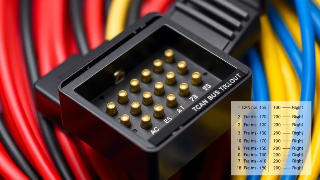
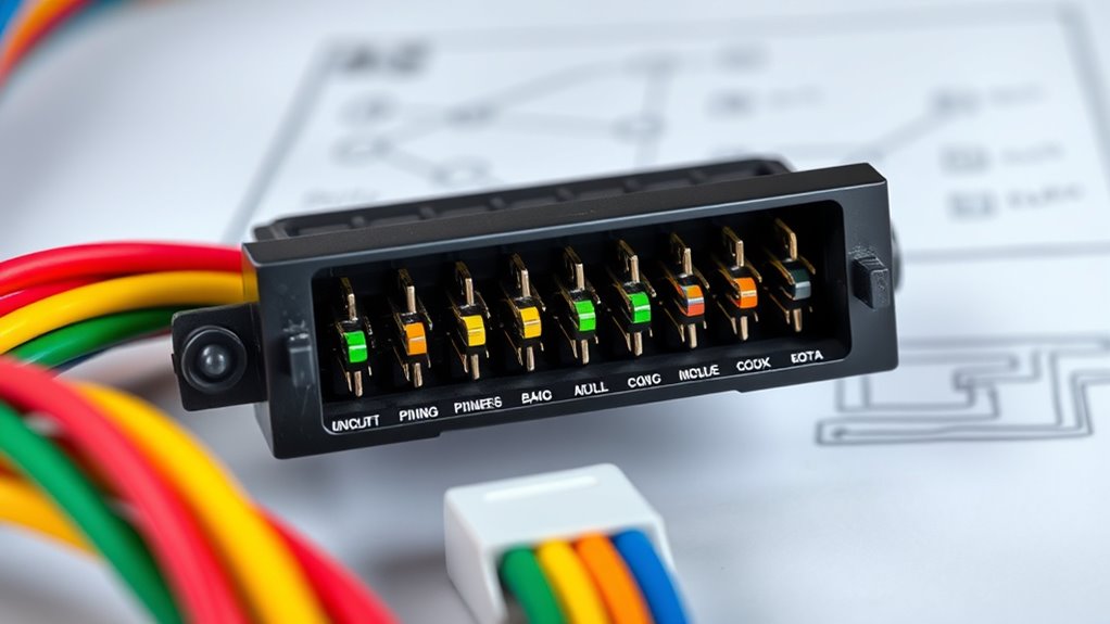
When planning your CAN bus network, you’ll want to pay close attention to pinouts, which are the specific arrangements of pins on connectors and transceivers. Correct pinout configuration guarantees proper connections between devices and prevents issues like miscommunication or damage. Typically, the CAN bus uses two main lines: CAN High and CAN Low. These lines are essential for differential signaling, which helps improve signal integrity by making the system more resistant to electrical noise. Proper pinouts ensure these lines are correctly wired and that terminators are placed at each end of the network to prevent signal reflections. Miswiring or incorrect pinouts can cause communication failures, data errors, or even damage to devices. That’s why understanding the specific pinout diagrams for your CAN transceivers and connectors is critical. When adding new devices, always verify the pinout compatibility to avoid disrupting the network’s operation.
Frequently Asked Questions
CAN CAN Bus Support Wireless Communication?
Yes, CAN bus can support wireless communication through wireless integration. You’ll need a device that converts the CAN protocol to a wireless standard, enabling seamless data transfer without physical wiring. This setup often involves protocol conversion, ensuring that the wireless signals are compatible with the CAN network. With the right hardware, you can achieve reliable wireless communication, making your system more flexible and easier to install in various environments.
How Does Temperature Affect CAN Bus Performance?
Think of your CAN bus like a delicate musical instrument; temperature effects can cause it to go out of tune. When temperatures rise or fall sharply, performance degradation can occur, leading to communication errors or data loss. High temperatures may cause electronic components to overheat, while cold can make signals sluggish. To keep your system in harmony, guarantee proper temperature management and protective measures, preventing performance degradation and maintaining reliable data transfer.
What Are Common Troubleshooting Methods for CAN Bus Issues?
You should start troubleshooting CAN bus issues by using diagnostic tools like oscilloscopes and CAN analyzers to check signal integrity. Look for abnormal voltages, noise, or irregular signal patterns that could indicate wiring problems or device faults. Check connector pins and wiring for damage or loose connections, and verify termination resistors are correctly installed. These steps help isolate faults quickly and guarantee reliable communication across the network.
Are There Any Safety Standards for CAN Bus Systems?
Yes, there are safety standards for CAN bus systems. You should follow electromagnetic interference (EMI) guidelines to prevent signal disruption and guarantee reliable communication. Proper grounding requirements are vital; they help reduce noise and avoid potential faults. Standards like ISO 11898 specify these practices, so you must adhere to them to maintain system safety, integrity, and compliance in your CAN bus installations.
How Does CAN Bus Handle Message Prioritization?
Did you know that CAN bus handles up to 1,000 messages per second? It uses message arbitration to manage message prioritization, ensuring high-priority data gets transmitted first. When multiple devices send messages simultaneously, the system uses priority messaging, where the message with the lowest identifier wins the bus access. This process prevents collisions and maintains efficient communication, making CAN bus highly reliable for real-time control systems.
Conclusion
Now that you understand CAN bus topology and pinouts, think of it as the nervous system of your vehicle or automation network—each wire a crucial pathway carrying signals like messages in a bustling city. Mastering these connections keeps everything running smoothly, preventing chaos and ensuring seamless communication. With this knowledge, you’re not just an observer but a conductor, orchestrating a symphony of signals that keeps your system alive and thriving.